

Picture 22 Suspension Elements: A star shaped drive gear was cut from plastic sheet. These are the parts for the bogies, return wheels and drivers.

Picture 23 Bogie Details: A block of thick plastic forms the mount and a thinner Evergreen tube makes the return roller.

Picture 23A Bogie Details: Further details added. The bolt heads are Grandt Line or Tichy Train model railroad bits. Note the green stuff to fill in the gaps. The spokes of the bogies will be filled in with green stuff and details added to the face plate and the swing arms with thin plastic rod.

Picture 24 Alumilite Components: A series of latex moulds were then made and parts cast out of Alumilite. The latex brushes on in many coats and is reinforced with cheesecloth. Shown are castings of the bogie unit and a return wheel. Since twelve bogie units were required, two moulds were made of the bogie unit. A simplified drive gear was also made and moulded.

Picture 25 Assembling Suspension: Support plates for the suspension were drawn out and drilled. The backs of the Alumilite castings were also drilled.

Picture 25A Assembling Suspension: Since I wasn’t sure how well the castings would adhere to the plastic; the drilled holes were to act as rivets when epoxy glue was used to assemble the components. The back view of the suspension plates shows the epoxy “rivets”.

Picture 26 Suspension Left and Right: The assembled suspension sides cut apart. Make sure you have left and right sides. There were a lot of air bubbles in the Alumilite parts. Some filler and some terrain-mud will resolve any issues.

Picture 27 Trackwork: The suspension plates were then trimmed to size and sanded for the curves. The plates will also be trimmed to show track sag over the return rollers.
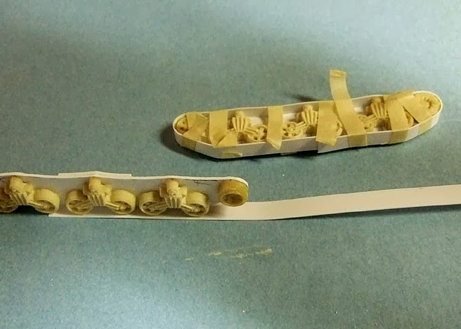
Picture 27A Trackwork: Evergreen strip plastic was formed over the track side plates. The liquid solvent glue holds the strip to the side plate. A bit of Crazy Glue bonded the track strip to the bogies. Liberal use of masking tape strips hold the strip in place until the glue dries.

Picture 27B Trackwork: Inside view. Note reinforcement strips top and bottom to hold the track strip in place. Spacer blocks will hold the track assembly to the lower hull.

Picture 27C Trackwork: Two assembled track units. At this point I was looking at many, many hours gluing many, many small strips of plastic to create the track links. Staring forlornly at my stock plastic box I came up with an alternative. (Remember that part about the only person you have to please is yourself and personal choices about how much work you want to do and how much detail you want to add?)

Picture 28 Track Details: I had some formed plastic roof tiles that had a suitable “bump” for the track links.
No comments:
Post a Comment